


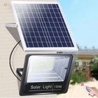


How Far Should Solar Path Lights Be from the Edge of a Walkway?

For most small residential ground-stake solar path lights, begin about 6–12 inches (15–30 cm) outside the finished edge of the walkway, then test the light at night before fully seating the stakes. This is a practical starting estimate, not a universal building-code or manufacturer requirement. The final distance should keep the fixture base out of the walking zone while allowing the light to reach the path, the solar panel to receive useful daylight, and lawn equipment to pass without striking the fixture.
The 6–12 Inch Starting Point
Measure the setback horizontally from the finished edge of the concrete, paver, gravel, or compacted walking surface to the center of the fixture’s stake or base. Do not measure from the outer edge of an overhanging light head. A broad light head may extend toward the path even when the stake itself is safely outside it.
| Starting setback | Where it may work | What to verify |
|---|---|---|
| 4–6 in (10–15 cm) | Compact fixtures beside a firm planting border with very limited space | The body and light head do not protrude into the route, and edging tools can pass safely |
| 6–12 in (15–30 cm) | Most residential concrete walks, paver paths, and garden borders | The beam reaches the path while the stake remains outside normal foot traffic |
| 12–18 in (30–46 cm) | Wide light heads, mowing strips, dense planting beds, snow-management areas, or driveway edges | The light still reaches the intended surface and the solar panel is not shaded |

These ranges are installation estimates rather than guaranteed dimensions. A narrow path, wheelchair route, gate opening, local code requirement, vehicle clearance area, or unusual fixture shape may require a different solution. When accessibility requirements apply, preserve the required continuous clear route instead of treating the fixture setback as the only measurement.
Measure From the Base, Not the Light Head
Ground-stake lights often have a head that is wider than the supporting post. If the stake is six inches outside the path but the head projects several inches toward the walking surface, the usable clearance is smaller than the stake measurement suggests.
Temporarily assemble one fixture at the intended height. Place it in the soil without fully driving the stake, then view it from above and from the direction people will travel. Check the outermost edge of the body, not just the post. A person carrying bags, a child running around a curve, or someone walking side by side may use more of the path width than a single careful walker.
The same principle applies beside raised edging. The stake may be outside the concrete while the light head hangs over a timber, stone, or metal border. Leave enough space to prevent contact with feet, garden carts, hoses, mower decks, and string trimmers.
Adjust the Offset for the Surface and Route
Straight concrete or paver walkways
A 6–12 inch starting setback usually provides a useful balance between beam coverage and physical clearance. Staggering the fixtures from one side to the other can define the route without producing an overly bright “runway” effect. If lights are installed on both sides, avoid placing every pair directly opposite each other unless the architecture calls for formal symmetry.
Curved garden paths
Curves need more breathing room because people naturally cut toward the inside edge. Keep the inside of a tight curve relatively open and favor the outside edge for fixtures where possible. Test the view from both travel directions; a light that appears safely outside the path from one direction may project into the sightline from the other.

Gravel and stepping-stone paths
The visible border of a gravel route can migrate as stones spread into the planting area. Measure from the normal walking line, not from a few scattered pieces of gravel. Beside stepping stones, keep fixtures outside the likely stride and away from the gaps where a person may step to regain balance.
Driveway edges
Driveway placement needs more clearance than a pedestrian-only path. Account for vehicle tires, mirrors, doors, snowplows, delivery vehicles, trash bins, bicycles, and mower turns. A fixture should not sit where a driver must make a perfect approach to avoid it. If adequate vehicle clearance pushes the light too far away for useful illumination, use another mounting location or a fixture designed for broader coverage.
Steps and level changes
Do not install a ground-stake light on a stair tread or in the landing’s walking area. Position it outside the route and aim the light toward the first tread, last tread, or change in level. The fixture should make the transition easier to recognize without becoming another obstacle.
Keep the Walking Zone and Maintenance Zone Clear
A path light must coexist with more than pedestrians. Before choosing the final position, identify where a mower wheel travels, where an edger or string trimmer is used, where irrigation lines run, and where snow or leaves are normally piled.
- Allow mower clearance: The mower deck may extend beyond the wheel path and can strike a fixture that appears safely inside a planting bed.
- Protect the stake from edging tools: Keep enough exposed soil around the base to see and maintain it.
- Avoid irrigation equipment: Do not force stakes through hidden tubing, wiring, landscape fabric fasteners, or utility routes.
- Stay out of drainage depressions: IP65 is not an immersion rating. Avoid standing water and low areas where runoff collects.
- Plan for plant growth: A small plant can shade the solar panel or block the beam later in the season.
- Preserve gate movement: Check the full swing of gates and doors rather than testing them only halfway open.
Where accessibility standards apply, the route itself must remain clear. The U.S. Access Board’s accessible-route guidance explains that required clear width cannot be reduced by obstructions. Requirements vary by property and jurisdiction, so confirm applicable local rules instead of using a garden-light estimate as a compliance measurement.
Test the Beam Before Fully Seating the Stake
Physical clearance is only half of the decision. The light must also land on the useful part of the route. Temporarily place several fixtures, let their batteries charge, and observe them after dusk before completing the installation.
- Check whether the near edge, center, or opposite edge of the path receives the useful light.
- Look for direct glare from normal standing and seated positions.
- Walk the route in both directions and around every curve.
- View steps, gates, transitions, and uneven surfaces from the direction people approach them.
- Confirm that plants, edging, and raised borders do not block the beam.
- Adjust the setback before changing the number of fixtures.
- After confirming the lateral setback, use the separate solar path-light spacing guide to plan the distance between fixtures.
Responsible outdoor lighting should be useful, targeted, low-level, controlled, and warm-colored where practical, according to DarkSky International’s outdoor lighting principles. Setting fixtures back from the walkway does not justify aiming unnecessary light toward windows, neighboring property, or the sky.
Solar Exposure Can Change the Best Position
A location can be physically perfect but unsuitable for an integrated solar panel. Roof overhangs, fences, shrubs, tree canopies, and neighboring structures may shade a light placed deep inside a planting bed. The U.S. Department of Energy’s solar guidance identifies excessive shade as an important solar-suitability consideration.
Observe the proposed location in the morning, around midday, and later in the afternoon. Seasonal foliage matters: an open position in winter can become deeply shaded during summer. If the best beam position receives insufficient daylight, move the fixture along the path or select a location with better exposure rather than placing the stake inside the walking surface.
How Fixture Height Changes the Decision

A taller fixture can cast light from a different angle and may reach the walkway from farther inside a planting bed. A lower fixture can provide a restrained pool of light but may be hidden by edging or plants. Height does not eliminate the need for physical clearance.
The current NoxLumin pathway-light design adjusts from 25 to 60 cm, approximately 10 to 24 inches. Test the intended height and setback together. At the taller setting, verify that the head does not project toward people or produce uncomfortable glare. At the shorter setting, confirm that mulch, leaves, grass, and border stones do not block the light or shade the panel.
The existing 10-inch versus 24-inch solar path-light guide provides a separate comparison of the two height approaches.
Where the NoxLumin Path Light Fits
The NoxLumin Brilliant 50 Lumens Solar Pathway Light is a ground-inserted, no-wiring outdoor fixture with a listed 50-lumen output, an adjustable 25–60 cm height, dusk-to-dawn operation, a 1000mAh battery, and an IP65 rating. Current light-color options are Warm White at 3000K and Cold White at 6500K.


The product charges fully in approximately 4–6 hours and delivers 6 to 8 hours of continuous operation. Actual results depend on solar exposure, weather, season, mode, battery condition, and panel cleanliness. Warm White is the more restrained everyday choice for most residential landscape settings; 6500K white may create stronger visual contrast but should still be aimed only where the additional contrast is useful.


This design makes sense beside garden paths, lawns, patios, planting borders, and pedestrian approaches where the stake can enter suitable soil and the integrated panel receives daylight. It is not the right installation for a paved surface that would require drilling, a vehicle tire path, standing water, or a deeply shaded border. Other verified outdoor configurations are available in the Solar Pathway & Garden Lights and Ground-Inserted Solar Lights collections.
Common Walkway-Edge Placement Mistakes
- Measuring from the light head: Measure from the stake or base, then separately check the complete fixture footprint.
- Placing the stake directly against concrete: This can leave no room for edging equipment and may let the body project into the route.
- Using one fixed distance everywhere: Curves, steps, driveways, gates, and mowing strips need different clearance.
- Fully driving every stake before testing: Temporary placement makes beam and glare corrections easier.
- Ignoring seasonal growth: Plants can block the light or shade the integrated panel.
- Assuming IP65 permits standing water: Keep fixtures out of drainage depressions and do not immerse or pressure-wash them.
- Confusing edge setback with fixture spacing: Lateral distance from the path and longitudinal distance between lights are separate decisions.
Frequently Asked Questions
How far should solar path lights be from a walkway?
Should solar path lights be placed on both sides of a walkway?
Can solar path lights be installed directly beside concrete?
How far should path lights be from a driveway edge?
Does path-light height change how far back it should be placed?
Can solar path lights be installed in mulch or wet soil?
How can I keep solar path lights from becoming a trip hazard?
Get more NoxLumin guides on Google
Add NoxLumin as a Preferred Source to help Google show you more of our outdoor lighting guides in Search and AI experiences.


Leave a comment